Inquiry
Form loading...

How to Choose the Right Center Line Valve?

Choosing the right Center Line Valve is a practical engineering decision, not a simple catalog exercise. The correct selection can reduce leakage, protect equipment, and simplify future maintenance. The wrong valve may look suitable on paper but fail under heat, pressure, vibration, or aggressive media.

R. W. Zappe, a respected valve-selection author, is often associated with this practical principle: “Select the valve for the service, not merely the pipe size.” That advice remains useful. A Center Line Valve should match the fluid, operating temperature, pressure range, flow direction, and required shutoff performance. Check the body material carefully. Stainless steel, ductile iron, and carbon steel behave differently in corrosive or abrasive systems. Seat material matters too. EPDM may suit water service, while other applications demand PTFE or a higher-performance option.

Start with the operating facts.

Do not guess.

Field experience shows that many valve problems begin with incomplete data. Engineers should confirm line size, flange standard, pressure class, actuator torque, cycling frequency, and available installation space. A valve installed beside a hot pump may need different materials than one used on a clean-water header. Maintenance access also deserves attention. It is easy to overlook until the valve must be removed during an urgent shutdown.

No selection method is flawless. Even experienced teams can focus too heavily on purchase price. A better review compares service life, replacement time, energy loss, and inspection requirements. This guide explains how to evaluate each factor and choose a Center Line Valve with stronger technical confidence.
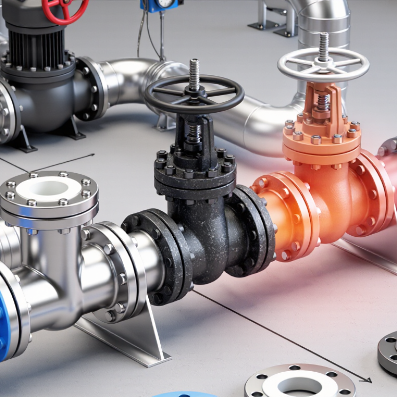
How to Choose the Right Center Line Valve?

Identify Centerline Design: Concentric Disc and 90° Quarter-Turn Operation

A centerline valve uses a concentric disc, with the stem placed through the disc’s center. This geometry supports a 90° quarter-turn operation. One full movement opens or closes the passage quickly. In practice, the short stroke can simplify actuator sizing and reduce installation space. It is a compact choice for water, air, and many general industrial services.

The seat matters as much as the disc. An elastomer seat surrounds the disc and can provide tight shutoff when correctly selected. Check temperature, chemical compatibility, pressure rating, and expected cycling frequency. ISO 5208 defines industrial valve leakage testing, but a test result does not guarantee field performance. Misaligned piping, damaged flanges, or excessive torque can still create leakage. Small details matter here.

Energy impact deserves attention. The U.S. Department of Energy reports that pumping systems may consume 25–50% of industrial facility electricity. A poorly selected valve can add unnecessary resistance and increase pump demand. However, a centerline design is not automatically efficient. Disc position, flow velocity, and pressure loss must be reviewed together. A quarter-turn action feels simple. The selection is not.

Before approval, compare the valve’s pressure-drop data with the system curve. Confirm the actuator’s closing torque, including seat friction and safety margin. I would also inspect the pipeline layout, because a centered disc may still obstruct flow near elbows or reducers. This is where catalogue assumptions can fail. Field conditions are less tidy than drawings.
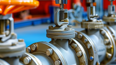
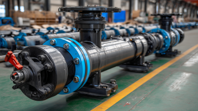
Compare ASME Class 150–600 Ratings with Pressure and Temperature

How to Choose the Right Center Line Valve?

ASME Class 150–600 ratings are not interchangeable pressure labels. They define allowable pressure at specific temperatures. For representative carbon steel valves, ASME B16.34:2022 lists approximately 285 psi for Class 150, 740 psi for Class 300, and 1,480 psi for Class 600 at 100°F. At 500°F, these values fall to about 170, 590, and 1,215 psi. The reduction is significant. Heat changes the decision.

Material group matters. Stainless steel, alloy steel, and carbon steel can have different pressure-temperature limits. Valve body material, wall thickness, bolting, gasket design, and end connection must match the applicable rating table. ASME B16.34 requires temperature-based verification, while ASME B16.5 governs many flanged dimensions and ratings. A Class 300 valve is not automatically safer than a correctly selected Class 150 valve.

Field specifications should state design pressure, operating temperature, fluid, cycling frequency, and pressure-test requirements. API 598 provides widely used inspection and testing guidance for valves, but it does not replace the pressure-temperature rating tables. A line carrying hot steam may exceed its rating after a temperature spike. That detail is easy to miss. I have seen selection reviews focus on pressure alone, then overlook thermal expansion and gasket limits. The rating table is essential, but it is not the whole decision. Verify the exact material class before ordering.

How to Choose the Right Center Line Valve?

Compare ASME Class 150–600 pressure ratings across operating temperatures. The chart uses representative ASME B16.34 pressure–temperature ratings for ASTM A216 WCB carbon steel valves, expressed in psi.

Selection guidance: Class 150 is suitable for lower-pressure service, while Class 300 and Class 600 provide progressively higher pressure capacity. Actual allowable pressure depends on valve material, temperature, design standard, corrosion allowance, and the manufacturer’s certified pressure–temperature table. Always verify the final selection against the applicable ASME edition and service conditions.

Choose Seat Materials by Media Compatibility and Temperature Range

How to Choose the Right Center Line Valve?

Seat selection starts with media compatibility and temperature, not valve size alone. Water, hydrocarbons, acids, oxidizers, and abrasive slurries attack seat materials differently. NIST Chemistry WebBook data places water’s critical point at 373.95°C. Steam service can therefore exceed common soft-seat limits quickly. Check the real operating temperature, including startup, shutdown, and cleaning cycles.

PTFE offers broad chemical resistance and often serves around -40°C to 260°C, depending on design and pressure. PEEK commonly handles higher mechanical loads and temperatures near 250°C. These figures are typical engineering ranges, not universal guarantees. Pressure, cycling, and chemical concentration can reduce them. ASME B16.34 pressure-temperature tables rate the valve assembly, but they do not automatically validate the seat material. That distinction is easy to miss.

For hydrocarbons, verify swelling and permeation data. For steam, inspect creep and hydrolysis resistance. For abrasive media, consider metal seats, accepting potentially higher leakage. ISO 23936-1 qualification practices can support non-metallic material evaluation in demanding oil and gas environments. API 607 fire-testing requirements also matter when combustible media and fire exposure are credible risks. I still request compatibility charts, test certificates, and actual cycle data from suppliers. Laboratory results may not represent a dirty pipeline. A small mistake here can increase torque, leakage, and maintenance costs.

How to Choose the Right Center Line Valve? - Choose Seat Materials by Media Compatibility and Temperature Range

Seat Material Approximate Temperature Range Recommended Media Compatibility Strengths Media or Conditions to Avoid Selection Guidance
PTFE
Polytetrafluoroethylene
−40 to +180°C
−40 to +356°F
Water, dilute acids, alkalis, many solvents, food and pharmaceutical fluids, high-purity chemicals Excellent chemical resistance
Very low friction and good non-stick performance
Molten alkali metals, elemental fluorine, some high-temperature fluorinating agents, severe abrasion and high mechanical loading A strong general-purpose choice when chemical resistance is more important than high-pressure or high-cycle mechanical strength.
RPTFE
Reinforced PTFE
−40 to +200°C
−40 to +392°F
Water, chemicals, hydrocarbons, solvents, steam in suitable valve designs and moderate abrasive services Excellent chemical resistance
Better dimensional stability, creep resistance and wear resistance than unfilled PTFE
Strong oxidizers or reactive fluorine compounds should be confirmed with the compound supplier; severe solids loading may still cause wear Consider it when PTFE compatibility is required but the valve will experience higher cycling, pressure or mechanical stress.
EPDM
Ethylene Propylene Diene Rubber
−45 to +150°C
−49 to +302°F
Hot water, cooling water, wastewater, dilute acids and alkalis, alcohols, glycols and many polar fluids Excellent for water and steam-related services
Good resistance to weathering, ozone and aging
Petroleum oils, mineral oils, fuels, diesel, gasoline and many hydrocarbon-based fluids Usually preferred for water-based media, but not for oil or hydrocarbon service. Verify the actual steam temperature and pressure before use.
FKM
Fluorocarbon Rubber
−20 to +200°C
−4 to +392°F
Mineral oils, fuels, diesel, hydraulic fluids, many hydrocarbons and selected concentrated acids Excellent oil and fuel resistance
Good high-temperature performance and low gas permeability
Hot water and steam, hot concentrated alkalis, amines, some polar solvents and certain low-temperature applications Choose FKM for oil and fuel service, but do not assume it is suitable for hot water or steam merely because its temperature rating is high.
NBR
Nitrile Rubber
−30 to +100°C
−22 to +212°F
Mineral oils, lubricants, hydraulic oils, fuels and many petroleum-based fluids Good oil and fuel resistance
Good abrasion resistance and cost-effective performance
Ozone and weathering exposure, strong oxidizers, aromatic solvents, ketones, esters and high-temperature water or steam A practical option for moderate-temperature oil and hydraulic applications where environmental exposure is controlled.
Silicone Rubber
VMQ
−60 to +180°C
−76 to +356°F
Dry air, ozone, selected food-contact fluids and some high- or low-temperature static applications Wide temperature flexibility
Excellent resistance to ozone, weathering and dry heat
Petroleum oils, fuels, concentrated acids and alkalis, abrasive media and high-pressure dynamic service Use primarily where a wide temperature range and environmental resistance are needed; confirm pressure and dynamic-cycle requirements.
PEEK
Polyether Ether Ketone
−40 to +250°C
−40 to +482°F
High-temperature water, hydrocarbons, chemicals, gases and selected abrasive or high-pressure services High temperature and mechanical strength
Good wear resistance and dimensional stability
Concentrated sulfuric or nitric acid, strong bases at elevated temperature and media outside the specific compound rating Consider PEEK when a polymer seat must withstand higher temperature, pressure or wear than standard elastomer seats can handle.
Metal Seat
Stainless steel, alloy or hard-faced design
Typically −29 to +400°C
−20 to +752°F
Design-dependent
High-temperature gases, abrasive slurries, hot oils, steam and services containing suspended solids High temperature and abrasion resistance
Suitable for applications where soft seats may deform or wear rapidly
Very clean shutoff requirements, corrosive media without suitable alloy selection and applications requiring bubble-tight sealing Use only after checking alloy compatibility, leakage class, thermal expansion, torque requirements and the valve manufacturer's pressure-temperature curve.

Important: Temperature ranges are typical engineering guidance, not universal limits. Actual allowable temperature, pressure, leakage class and cycle life depend on the seat compound, valve construction, shaft and disc materials, media concentration, abrasive content and applicable standards. Always verify the complete pressure-temperature rating and chemical compatibility for the specific service.

Calculate Valve Size Using Cv, Flow Rate, and Line Velocity

How to Choose the Right Center Line Valve?

Choosing a center line valve starts with process data, not pipe diameter. Record flow rate, fluid density, inlet pressure, outlet pressure, temperature, and allowable pressure loss. For liquids, a common preliminary equation is Cv = Q√SG/√ΔP Here, Q is gallons per minute, SG is specific gravity, and ΔP is pressure drop in psi. Use one consistent unit system. Mixed units can create a confident but incorrect result.

After estimating Cv, check the line velocity. Convert flow into actual volumetric units, then calculate v = Q/A where A is the internal pipe area.

A valve may have the correct Cv but still produce excessive velocity through a reduced opening. High velocity can cause noise, vibration, erosion, or liquid cavitation. Low velocity can reduce control sensitivity and allow solids to settle. Compare the result with project limits and fluid behavior. Do not size the valve by nominal pipe size alone. Gas service needs compressible-flow calculations because density changes across the valve.

Tips: Use normal and maximum flow rates. Check the required Cv at both conditions. Review pressure loss, shutoff pressure, flashing risk, and actuator load. Ask an experienced process engineer to verify the calculation. I would also recheck the result after installation, because real piping rarely behaves exactly like a spreadsheet. Mistakes are easier to correct before commissioning.

Verify ISO 5211 Actuation and ISO 5208 Leakage Requirements

Choosing a center line valve starts with two checks: actuation fit and verified shutoff performance. ISO 5211 defines the mounting interface, drive dimensions, and flange geometry between valve and actuator. It does not prove that an actuator has enough torque. Measure breakaway, running, and seating torque under actual pressure. Add a documented safety margin. A clean square drive can still fail when cold fluid increases friction. That detail is often missed.

Ask for the valve’s ISO 5211 size, stem dimensions, actuator torque curve, and mounting orientation. Compare these records, not catalogue headlines. During commissioning, record opening time, closing time, supply pressure, and abnormal vibration.

In field work, I would also check manual override engagement before energizing the actuator. It is a small step. It prevents an expensive surprise.

ISO 5208 provides pressure-test procedures and leakage rates, but “tested to ISO 5208” is incomplete. Request the selected leakage rate, test pressure, medium, duration, and acceptance result. The U.S. Department of Energy’s Improving Compressed Air System Performance sourcebook reports that leaks can waste 20–30% of compressor output. That figure concerns compressed-air systems, not every valve, yet it shows why leakage deserves measurement.

A pressure gauge alone is not enough. Repeat the test after cycling; seals can behave differently after installation. My preference is clear evidence over a perfect-looking datasheet, though that approach still needs review when service conditions change.